|
Now that the outside of this
gun has been explored, lets take a look into its internal design.
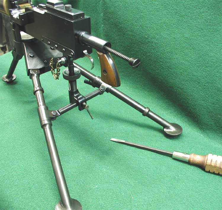
The first thing that had to be done was to find
out how it
could come apart. It disassembles totally different
than the later production guns. The buffer tube is actually the key to the
disassembly. When the buffer screw is turned out we find it works as a recoil
spring retaining device. Without the recoil spring and guide removed the back
plate with pistol grip can not be slid upward.
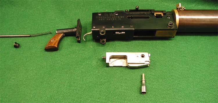
When the recoil spring and
guide rod are removed the pistol grip assembly can be slid upward and out of
the back of the receiver. The bolt can be moved backward so the cocking handle
lines up with the removal pocket in the cocking slot. With the handle removed,
the bolt can be removed all the way out. Notice the massive cutout in the rear
end of the bolt assembly. This is for the hammer rotation of the trigger pack.
There is a small "buffer" spring in the back of the bolt to reduce
recoil. This spring was removed in the later guns because of the extended length
of the bolt cycle stroke per shot and recoil reduction was not a concern
anymore. 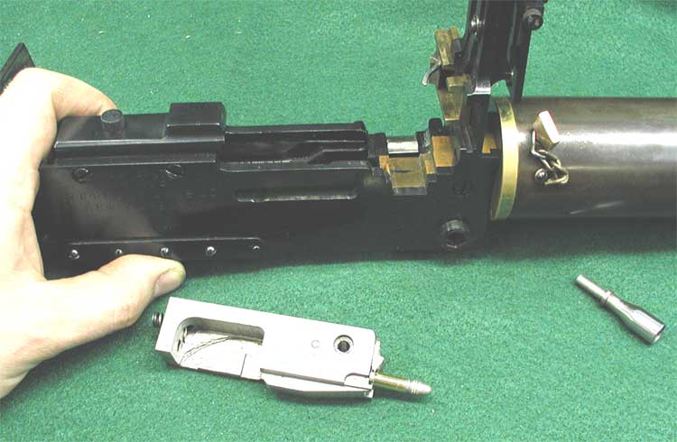
This
picture above shows the first thoughts of the left side plate cam design. It
simply is a small milled path that drives the extractor downward on the rear
stroke of the bolt. The production guns have a forward extractor manipulation
design as well as a spring loaded "flipper" that made a positive cam
track path for each bolt cycle. Also seen here is a small leaf spring in the
cam track that allows extractor pressure on the round in the feed tray, this
is till used in the production models. 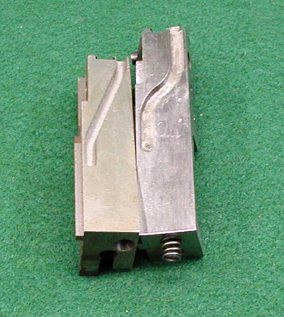
This
picture shows the cam slot in the top of the bolts as well as the bolt length
differences. The cam transition on the bolt on the left is the current design
which makes the top slide react in a smooth fashion when the bolt cycles. The
right (prototype) cam groove has a violent reaction to the top slide when its
bolt cycles during firing. Notice the buffer spring in the prototype bolt. 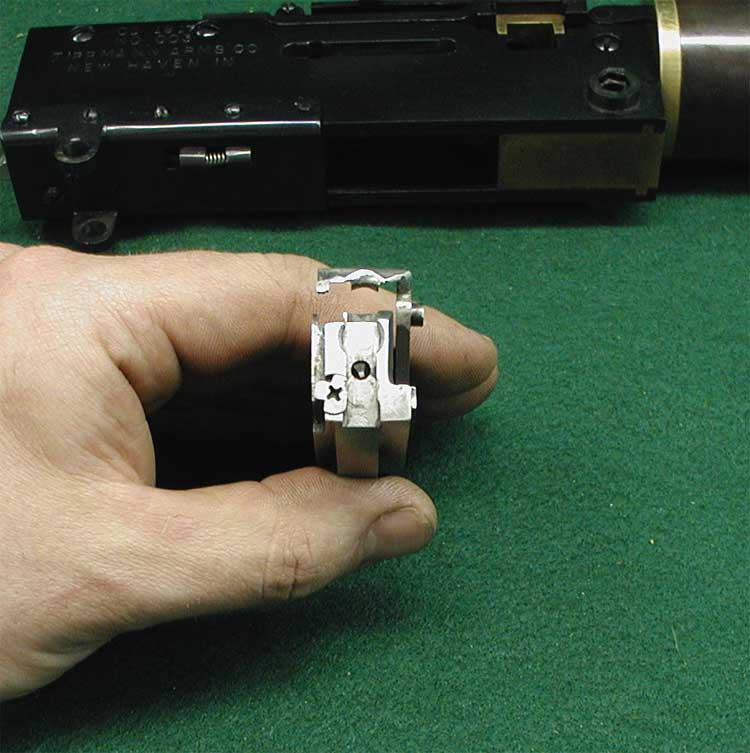
Above
is the heart and soul of the guns mechanism, the extractor. One of the
problems with a Browning belt-fed design is the fact that the cartridge needs
to be held in position when it is being chambered. This extractor design did
three things. This small delicate part needed to extract a round from the belt
that was sitting in the feed tray and keep it captivated in the T-slot of the
bolt face. It then had to slide the round down the bolt T-slot by means of the
drive lug riding in the cam track milled into the left side plate. The rim of
the 22 cartridge was captivated in the T-slot by a "switch" that was
activated by the far outside of the extractor. The little extractor ear would
push down on the "screw" type switch temporarily closing the T-slot.
As the nose of the cartridge was entering the chamber the "switch"
was released by a small lug that pushed the "switch" upward again
thus resetting it for the next round to travel thru. This lug will be shown in
a picture further down. The picture below shows how a cartridge could be
captured inside of the T-slot by the extractors manipulation. This entire
process was timed so finely and was no doubt very time consuming to
manufacture. 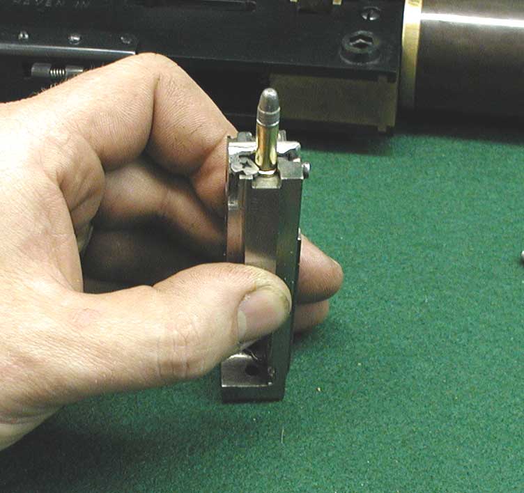
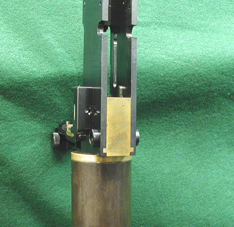
The
picture above is a close up of the "lug" mentioned in the extractor
operation above. This lug is in the right side plate and sticks out the rear
of the breech block. It engages the "switch" in the face of the bolt
to release the empty cartridge so it can fall out the T-slot. 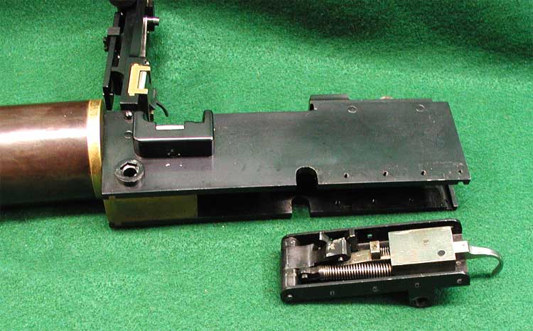
Here
is the trigger/hammer pack disassembled from the bottom of the gun. The hammer
is shown in the "cocked" position. This model had NO provision for a
safety what so ever. 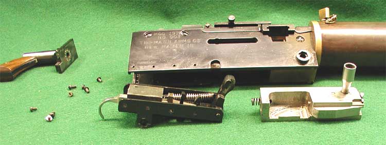
The
above picture is of the trigger/hammer pack taken out of the gun and it is in
the fired position. Well,
I hope you have enjoyed this little tour of the past. It was a true pleasure
to see the insides of this gun and to see what the first ideas were that led
to its production. If any of you might have a similar model like this with
unique features, Please let us know, we would like to include it in this
archive page. return to gallery
|